


How to Wire Emergency Vehicle Lighting: 2026 Guide
Table of Contents
- What You'll Need Before You Start Wiring
- Emergency Vehicle Light Wiring Diagram: Planning Your Circuit
- Fusing Emergency Lighting Circuits Safely
- Routing Cables and Firewall Penetration
- Choosing the Best LED Strobe Lights for Trucks
- Grounding, CAN Bus Integration, and Post-Install Testing
- Common Mistakes to Avoid
- Frequently Asked Questions
Last Updated: September 30, 2026
What You'll Need Before You Start Wiring
Learning how to wire emergency vehicle lighting starts with the right parts on the bench, and knowing how to wire emergency vehicle lighting is really about prep. A clean install depends on prep, not speed. Gather these first:
- American Wire Gauge (AWG) wire sized to each light's current draw
- Inline fuse holders and a fuse block for circuit protection
- Ring terminals, butt connectors, and heat shrink tubing
- Wire loom and grommets for chafe protection
- Weatherproof connectors and dielectric grease
- Relay harness and a switch controller
- Multimeter for multimeter testing
- Wiring diagram and a battery disconnect tool
Lay everything out before you cut a single wire.
Emergency Vehicle Light Wiring Diagram: Planning Your Circuit
A good emergency vehicle light wiring diagram answers three questions before you cut wire: what draws power, how much, and from where. Map every light to its own fuse slot, then trace the run from battery to switch to fixture. This planning step is where most builds succeed or fail.
Reading American Wire Gauge and Voltage Drop
American Wire Gauge (AWG) is the standard sizing system for wire thickness. Thicker wire carries more current with less resistance. Undersized wire causes voltage drop, which dims lights and heats cable.
Use this quick reference before you buy wire:
| Load (amps) | Run under 10 ft | Run 10-20 ft | Run over 20 ft |
|---|---|---|---|
| Up to 5A | 18 AWG | 16 AWG | 14 AWG |
| 5-10A | 16 AWG | 14 AWG | 12 AWG |
| 10-15A | 14 AWG | 12 AWG | 10 AWG |
| 15-20A | 12 AWG | 10 AWG | 8 AWG |
Relay vs. Direct Switch Wiring
Relay vs. direct switch wiring is the biggest decision in your diagram. A relay harness lets a small switch control a large electrical load. Direct switch wiring sends full current through the switch itself.
Fusing Emergency Lighting Circuits Safely
Fusing emergency lighting circuits protects the vehicle and the crew. Every positive run needs an inline fuse or a slot on a fuse block, placed as close to the power source as possible. The fuse should match the wire's amperage rating, not the light's.
- One fuse per circuit, never one fuse for the whole system
- Keep spare fuses in the cab
- Label every fuse slot on the block
- Test the fuse block with a multimeter before connecting lights
Routing Cables and Firewall Penetration
Route cables away from heat, moving parts, and sharp metal. Use cable routing paths along factory harnesses where possible. Keep positive and negative ground runs together to reduce induced noise. Where a run crosses the engine bay, add split loom and secure it every 12-18 inches with cushioned clamps so vibration never rubs insulation against a bracket.
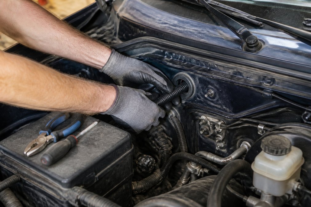
Vehicle-Specific Firewall Penetration Without Breaking Seals
The goal is a pass that keeps the cabin weather-tight, does not chafe the wire, and does not disturb the factory harness. A repeatable method:
- Find an existing pass first. Most trucks and SUVs already have a factory grommet or a blank plug in the firewall. Reusing one is faster and safer than drilling new metal. Look near the main harness bundle, the steering column, and the parking brake cable.
- If you must drill, use a step bit. A step bit gives you a clean, round hole and lets you stop at the exact diameter. Deburr both sides with a deburring tool or a larger bit turned by hand, a sharp lip will saw through insulation over time.
- Seal the pass. A rubber grommet alone is not enough on a vehicle that sees rain, dust, or engine-bay heat. Use a grommet plus a bead of automotive-grade silicone or butyl sealant around the wire where it enters the grommet. Some installers prefer a bulkhead fitting with a compression nut for a fully sealed, serviceable pass.
- Leave a service loop. Give the wire 3-4 inches of slack on both sides of the firewall so engine torque and body flex do not pull the wire taut.
- Re-seal the factory grommet if you reused it. Pushing a new wire through an existing grommet opens a gap. Pack the opening with dielectric grease and seal the outer edge with silicone.
Grommets, Wire Loom, and Weatherproof Connectors
Grommets protect wire where it passes through metal. Without one, vibration slowly cuts the insulation and creates a short circuit. Wire loom adds a second layer of chafe protection along the run. Use split loom in the engine bay and braided sleeving in the cabin where abrasion is lighter.
- Seal every firewall pass with a grommet plus sealant
- Wrap full runs in wire loom and secure every 12-18 inches
- Grease every exterior connector
- Leave a drip loop before connectors that sit low in the engine bay
- Keep positive and ground runs paired to reduce radio interference
Choosing the Best LED Strobe Lights for Trucks
The best LED strobe lights for trucks balance brightness, current draw, and mounting options. LED strobes draw far less power than older halogen units, which eases the load on your wiring. Look for units rated for vibration and weather exposure.
Match the light to the job:
- Grille and surface mounts for front warning
- Light bars for broad coverage
- Hideaway strobes for clean installs
- Perimeter lights for side visibility
Grounding, CAN Bus Integration, and Post-Install Testing
A clean grounding point on bare metal makes or breaks the install. Scrape paint down to shiny steel, use a star washer to bite into the metal, and torque the bolt to spec. A weak ground causes flicker, false triggers, and hard-to-trace faults that mimic a bad light. Run a dedicated ground wire back to a known chassis ground for each high-draw circuit rather than relying on a self-tapping screw into sheet metal.
Multimeter Testing and Short Circuit Prevention
Test before you power up. Multimeter testing confirms continuity, correct polarity, and no short circuit prevention gaps. Check resistance to ground on every positive run before the first fuse goes in, a reading near zero ohms means a dead short you have not found yet.
Post-Installation Testing Protocols
- Continuity check on every circuit with the fuse removed, confirms the run is intact and not shorted to ground.
- Polarity check at each light before connecting it, reversed polarity on an LED will not light and can damage the driver.
- Voltage check under load at each light with the engine running, compare to battery voltage to measure voltage drop. A drop of more than about 0.5V on a short run points to undersized wire or a bad ground.
- Flicker test with the engine running and accessories on, flicker usually means a ground issue or a CAN bus conflict.
- Full lighting pattern test on the controller, cycle every mode, every flash pattern, and every zone.
- Thermal check on the fuse block and relay after 10 minutes of continuous operation, warm is normal, hot is a problem.
- Radio and electronics interference check, key the radio, run the siren, and confirm no noise on the audio system or false triggers on other modules.
- Road test at night, confirm aim, visibility, and that no warning lights appeared on the dash.
The NHTSA guidance on emergency lighting visibility explains why correct light placement and output matter for on-road safety.
Common Mistakes to Avoid
- Undersized wire causing voltage drop and heat
- No relay on high-draw circuits
- Missing grommets at firewall passes
- Fusing for the device instead of the wire
- Poor grounding on painted metal
- Tapping CAN bus wires instead of switched power
- Skipping the post-install test and finding faults in the field
For departments that need this done right the first time, Traffic Safety System offers installation services and custom fabrication for special projects. Our veteran-owned team has supported law enforcement, fire, and industrial fleets.
Frequently Asked Questions
What gauge wire should be used for emergency vehicle lights?
Gauge depends on current draw and run length. A single 20-watt LED strobe drawing about 1.5 amps can use 18 AWG for short runs. A full light bar pulling 15 amps over 15 feet needs 12 AWG or thicker. Check American Wire Gauge charts and keep voltage drop under 3% to avoid dim or flickering lights. When in doubt, size up one gauge.
Do I need a relay when wiring emergency vehicle lights?
Use a relay whenever the total current draw exceeds the switch rating, typically above 10 to 15 amps. A relay harness lets a low-current switch control a high-current circuit, protecting the switch and reducing voltage drop. Small single strobes under 5 amps can run on a direct switch, but any multi-light setup should use a relay.
How do I protect emergency lighting circuits with fuses?
Place an inline fuse within 12 inches of the battery or fuse block on the positive leg. Size the fuse at 125% of the circuit's normal current draw, never higher than the wire's amperage rating. A 15-amp circuit uses a 20-amp fuse. Keep spare fuses in the vehicle and label each circuit for fast troubleshooting.
Is it legal to install emergency lights on a personal vehicle?
Laws vary by state. Most states restrict red, blue, and flashing white lights to authorized emergency vehicles. Amber lights are generally allowed on work trucks and trailers. Check your state motor vehicle code before installing any emergency vehicle lighting, and never use authorized colors on a non-authorized vehicle.
Wiring emergency vehicle lighting leaves no room for guesswork. A weak ground or a missing relay can take a rig out of service when it matters most. Traffic Safety System provides high-quality lighting solutions, installation services, and custom fabrication built for demanding conditions. Get started with Traffic Safety System and equip your fleet with lighting you can trust.